
How to wire stepper motors?
Stepper motors convert electrical impulses into precise mechanical rotation. Proper connection of the motor coils to the drive is essential for precise motion control. This overview covers stepper wiring basics.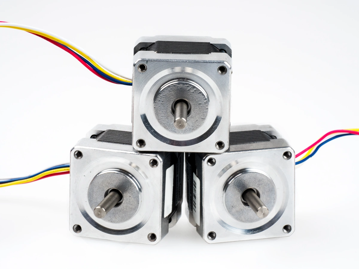
Motor type
Stepper motors come in bipolar, unipolar, and hybrid configurations. Four- or six-wire bipolar motors are the most common. They can be connected in series or parallel. Unipolar motors have center-tapped coils.
Coil line identification
Motor coils form electromagnets to orient the rotor. On 4-wire motors, measure the resistance to find the two pairs. See the data sheet for guidance on 6- and 8-wire motors. Mark pairs A and B.
Drive Output Connections
Connect A+ to one end of coil A and A- to the other end. Repeat for the B+ and B-wires of coil B. Drive sequences A and B cause the motor to step.
Fixed wires
Tie wires securely in pairs using ties or lanyards. Prevent bare leads from coming loose. Heat shrink tubing helps to strengthen connections.
Verify the direction of rotation
Apply power to the drive to verify that the motor is rotating correctly. If reversed, swap the A+ and A-connections to reverse the magnetization of coil A.
Conclusion
Correctly wiring stepper motors to match drive outputs ensures correct phase fixing and rotary motion. Planning wiring can avoid electrical problems. Take precautions when handling these sensitive components.
Leave a Reply