Detailed explanation of the structure of the stepper motor and three control modes
In today's intelligent era, stepper motors are widely used for their unique open-loop position control performance. Various equipments have certain requirements on the smoothness of the output torque of the stepper motor during its rotation.
The stability of rotation is not only related to the body structure of stepper motor, but also closely related to the control mode of stepper motor. This article will introduce the bipolar stepper motor and its structure and control mode.
Basic components of bipolar stepper motor
Stepper motors are brushless DC (BLDC) motors that rotate gradually in equal steps. A bipolar stepper motor, on the other hand, is a stepper motor that has one winding per phase, specifically a two-phase, four-wire stepper motor. It consists of two main components, the stator and the rotor (see Picture 1).
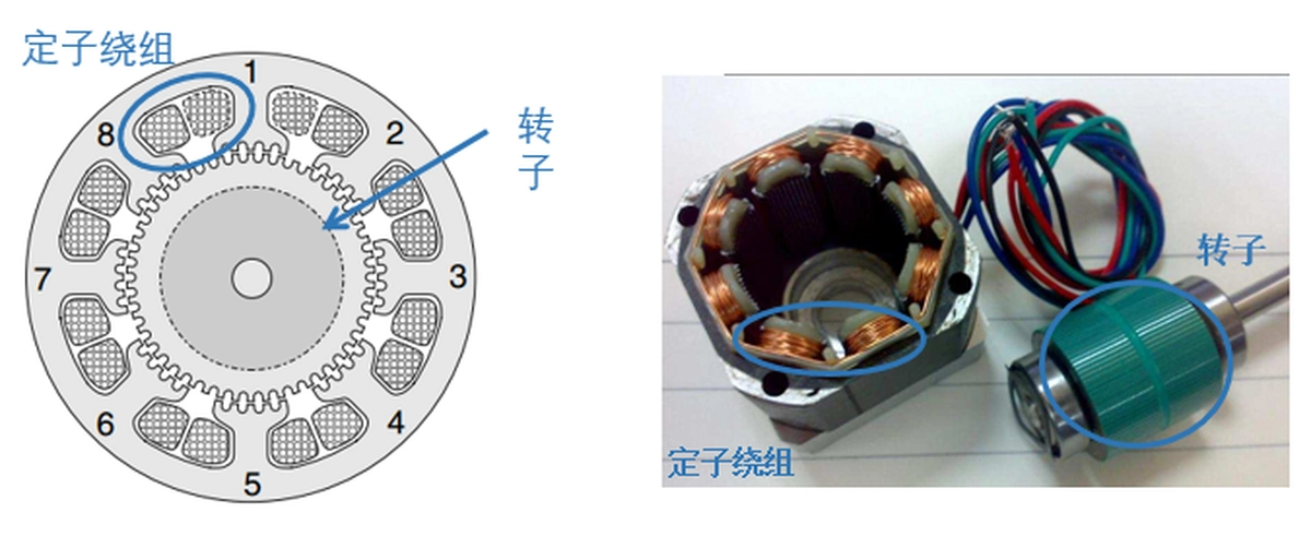
The stator is the stationary part of the motor. The stator is wound with two-phase bipolar windings with five teeth on each stator core (see picture 1).
The A-phase windings start at stator 1 and are wound onto stators 3, 5 and 7 (see Fig. 2). It should be noted that the winding direction is the same for stators 1 and 5, and the winding direction is the same for stators 3 and 7. These two groups (stators 1 and 5, and stators 3 and 7) are wound in the opposite direction. the B-phase windings are wound on the same principle, with stators 4 and 8 in one group, and stators 2 and 6 in the other.

The rotor is usually fitted with axially magnetised permanent magnets. The structure of the rotor is shown in picture 3.
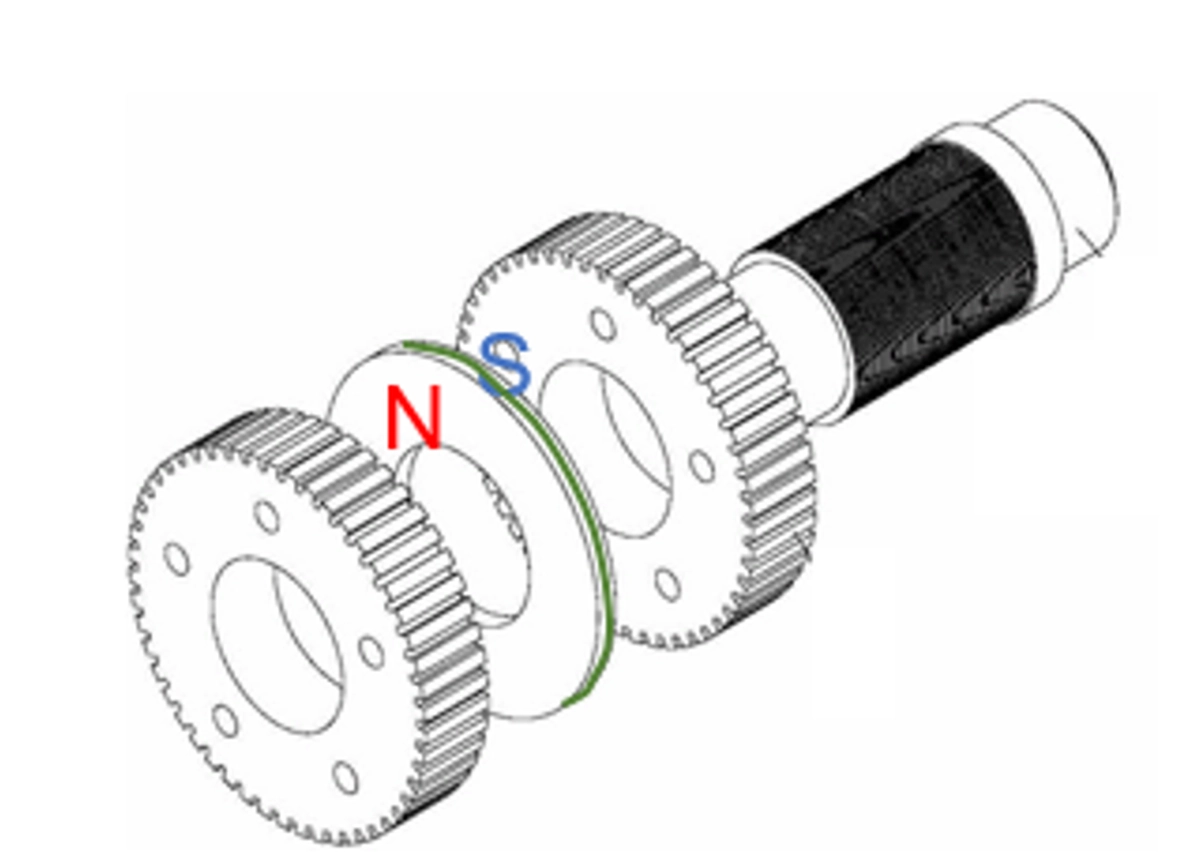
Picture 4 illustrates a side cross-section of the rotor.
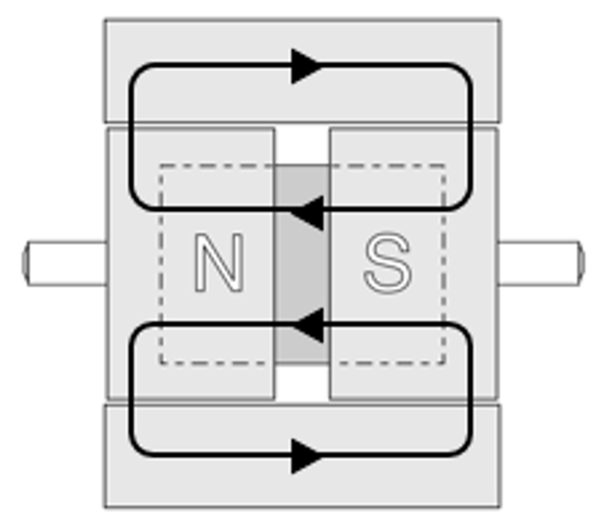
The magnetic lines of force of the permanent magnets form a closure within the body of the motor. Due to the magnetic lines of force and the magneto-resistive effect, the stepper motor has a locking torque even when it is not energised (see picture 4).
The rotor has 50 teeth and, in relation to the stator gear, has a stepping angle of 1.8 degrees due to the number of teeth and phases (see Fig. 5). Stepping angle: The mechanical angle at which the rotor of the stepper motor advances after the electrical cycle has completed 90 degrees.
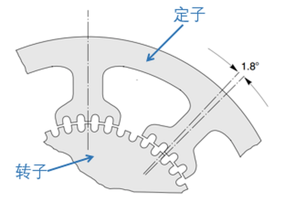
Stepping mode
In order to facilitate the explanation of the subsequent control modes, we have simplified the complex structural diagram into a schematic (see picture 6).
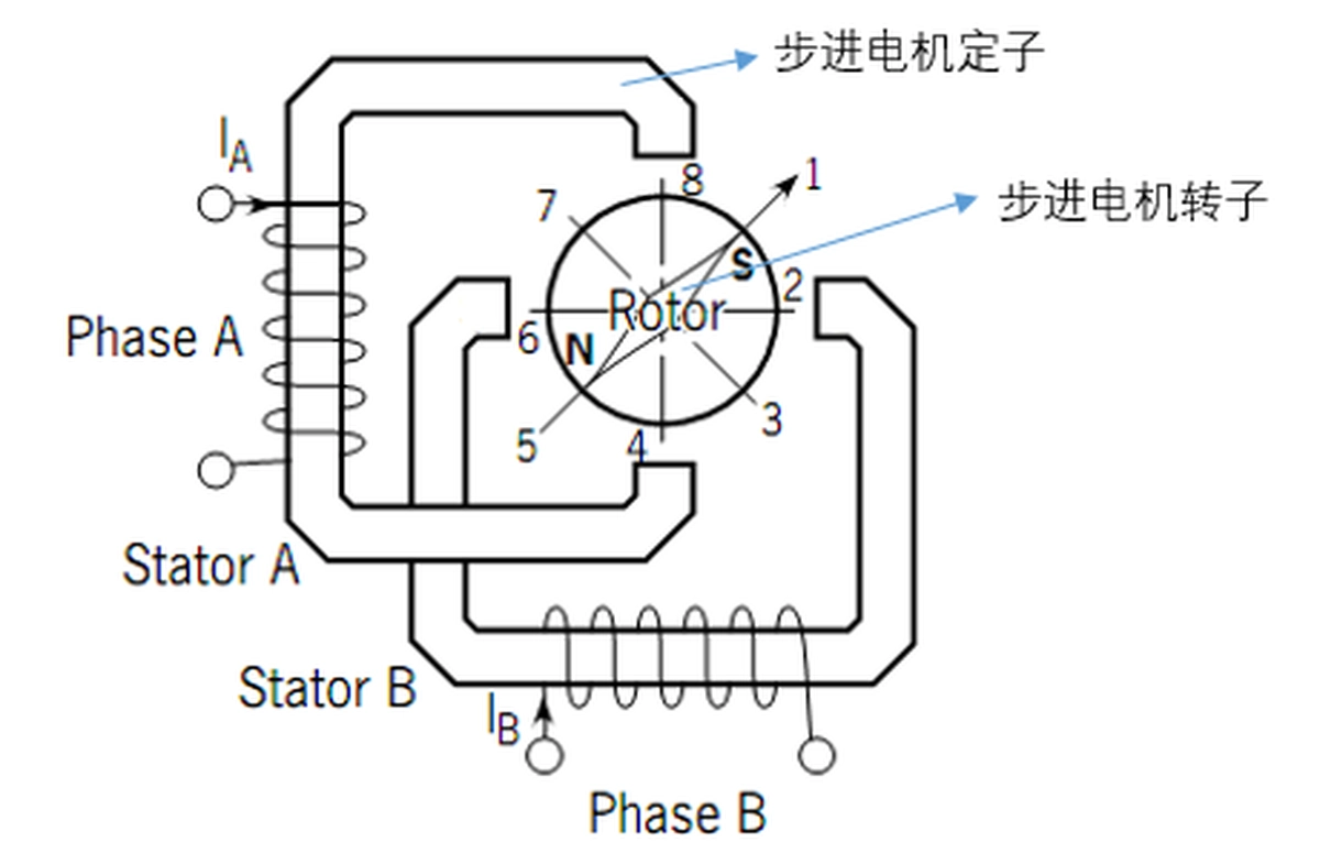
The stator and rotor of a stepper motor can be thought of as both having only one tooth, which makes the stepper motor drive different from other motors. This method is called dual full-bridge drive, where the A-phase winding is connected to the first full-bridge drive and the B-phase winding is connected to the second full-bridge drive (see picture 7).
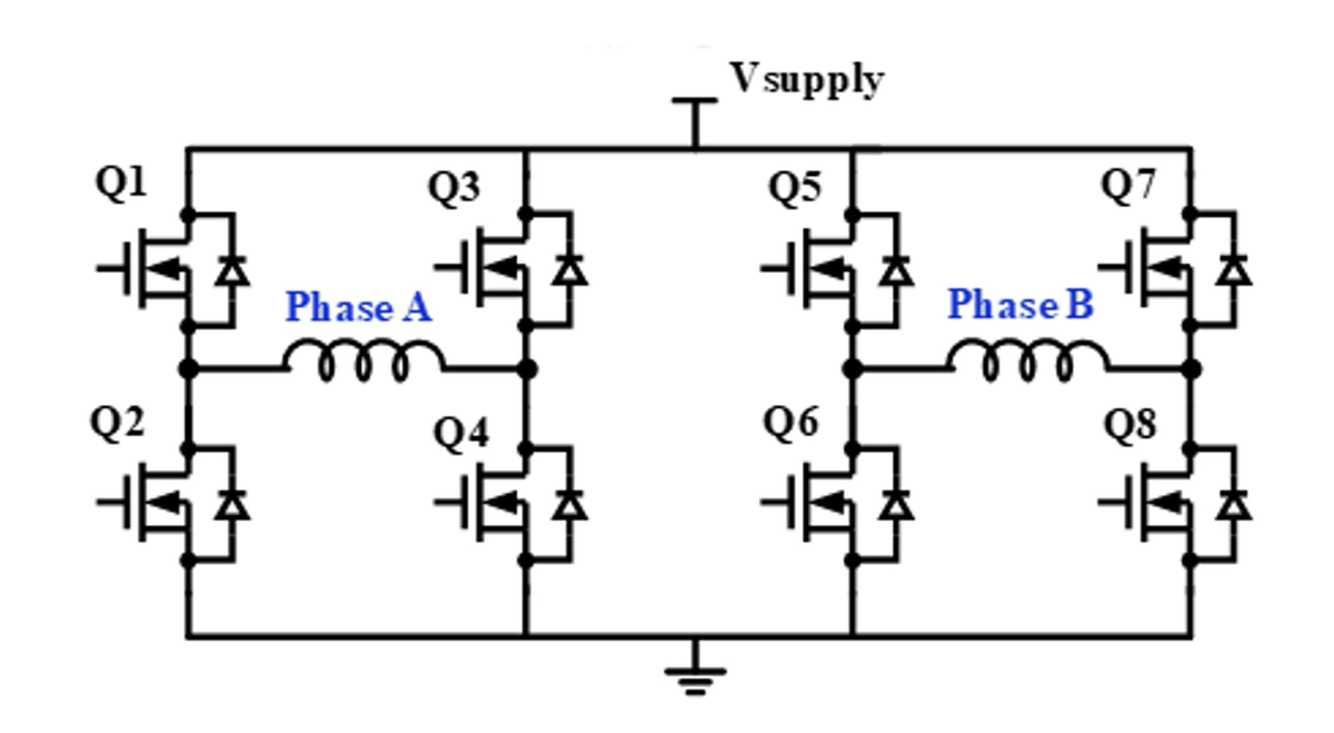
Bipolar stepper motors have three control modes: single-phase stepping, full-step stepping and half-step stepping (see Table 1).

Single-phase stepping
When phases A and B are energised in sequence according to the single-phase stepping pattern, the stator magnetic field changes accordingly and the rotor rotates due to polarity attraction. The energisation sequence of phases A and B (AB) and the rotor rotation position are described in detail in Table 1.
The single-phase stepping process consists of three steps, as described below:
When A is energised, the drive current flows from Q1 to Q4. At this point, the top end of stator A is N, the bottom end is at S, and the rotor rotates to position 8 (see Fig. 6).

Leave a Reply