Stepper motor forward and reverse line changing method
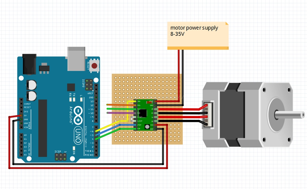
Stepper motor is a type of motor commonly used for precise motion control. It has the ability to rotate in both directions, which is also one of the common control methods of stepper motor. This is mainly achieved by changing the polarity of the power supply or the direction of the current flow. Rewiring refers to changing the way the stepper motor is connected to the power supply in order to change the current sequence of the coils, thereby changing the direction of motion of the stepper motor by activating the coils in different sequences. If you need to control the forward and reverse rotation of the stepper motor, you need to change the wiring of the stepper motor. There are many methods of rewiring, and one of the common rewiring methods will be detailed below.
Method of Changing Lines

First, it is necessary to understand the coil arrangement order of the stepper motor. A stepper motor typically consists of two adjacent coils, each with a terminal. In a four-wire stepper motor, there are two coils, referred to as the "A" coil and the "B" coil. Each coil has two terminals labeled as "A1", "A2" and "B1", "B2". These terminals will be connected to the power supply to activate the motor.
In this switching method, we will use two power lines, labeled as "Vcc" and "Gnd", to drive the stepper motor. Stepper motors typically require a controller (such as a driver or microcontroller) to control the power connection method.
Step 1:
Connect "A1" to "Vcc", and connect "A2" to "B1". At this point, the power connection is as follows: "Vcc" - "A1" - "A2" - "B1" - "Gnd".
Step 2:
Connect "B2" to "Vcc" and disconnect "A1". At this point, the power connections are as follows: "Vcc" - "B2" - "A2" - "B1" - "Gnd".
Step 3:
Connect "A2" to "Vcc", disconnect "B1". At this point, the power connections are as follows: "Vcc" - "B2" - "A2" - "Gnd".
Step 4:
Disconnect "B2" and reconnect "A2" and "A1". At this point, the power connections are as follows: "Vcc" - "A1" - "Gnd".
By following the above steps to connect the power lines, the forward and reverse rotation of the stepper motor can be achieved. First, it is necessary to ensure that the connection of the power lines is correct to avoid short circuits and other damages to the motor circuit. Additionally, it is also important to ensure that the power lines can provide enough current to drive the stepper motor.
It should be noted that the wiring method of stepper motors may vary depending on the specific motor model and manufacturer. Therefore, when operating a stepper motor, it is recommended to refer to the motor's technical manual or the manufacturer's instructions to ensure the correct wiring method is used.
Conclusion
In general, the method of changing the wiring of a stepper motor is a method of achieving the forward and reverse rotation of the motor by changing the sequence of coil current connections. By connecting the power lines in different ways, the activation sequence of the stepper motor coils can be changed, thereby changing the direction of motion of the motor. When performing the rewiring operation of the stepper motor, it is necessary to carefully read the technical manual of the motor or the manufacturer's instructions, and ensure the correct connection of the power lines and an adequate supply of current.


Leave a Reply