Understanding stepper motor control in one article
Stepper motors, also known as steppers, use the principles of electromagnetism to convert electrical energy into mechanical energy, and people began using them as early as the 1920s. With the growing popularity of embedded systems (e.g., printers, disk drives, toys, windshield wipers, vibrating pagers, robotic arms, and video recorders), the use of stepper motors has begun to skyrocket. Whether in the industrial, military, medical, automotive, or entertainment industries, stepper motors are sure to come in handy whenever an object needs to be moved from one position to another. Stepper motors come in many shapes and sizes, but regardless of shape or size, they can be grouped into two categories: variable reluctance stepper motors and permanent magnet stepper motors. This article focuses on the simpler and more commonly used permanent magnet stepper motors.
Stepper motor construction
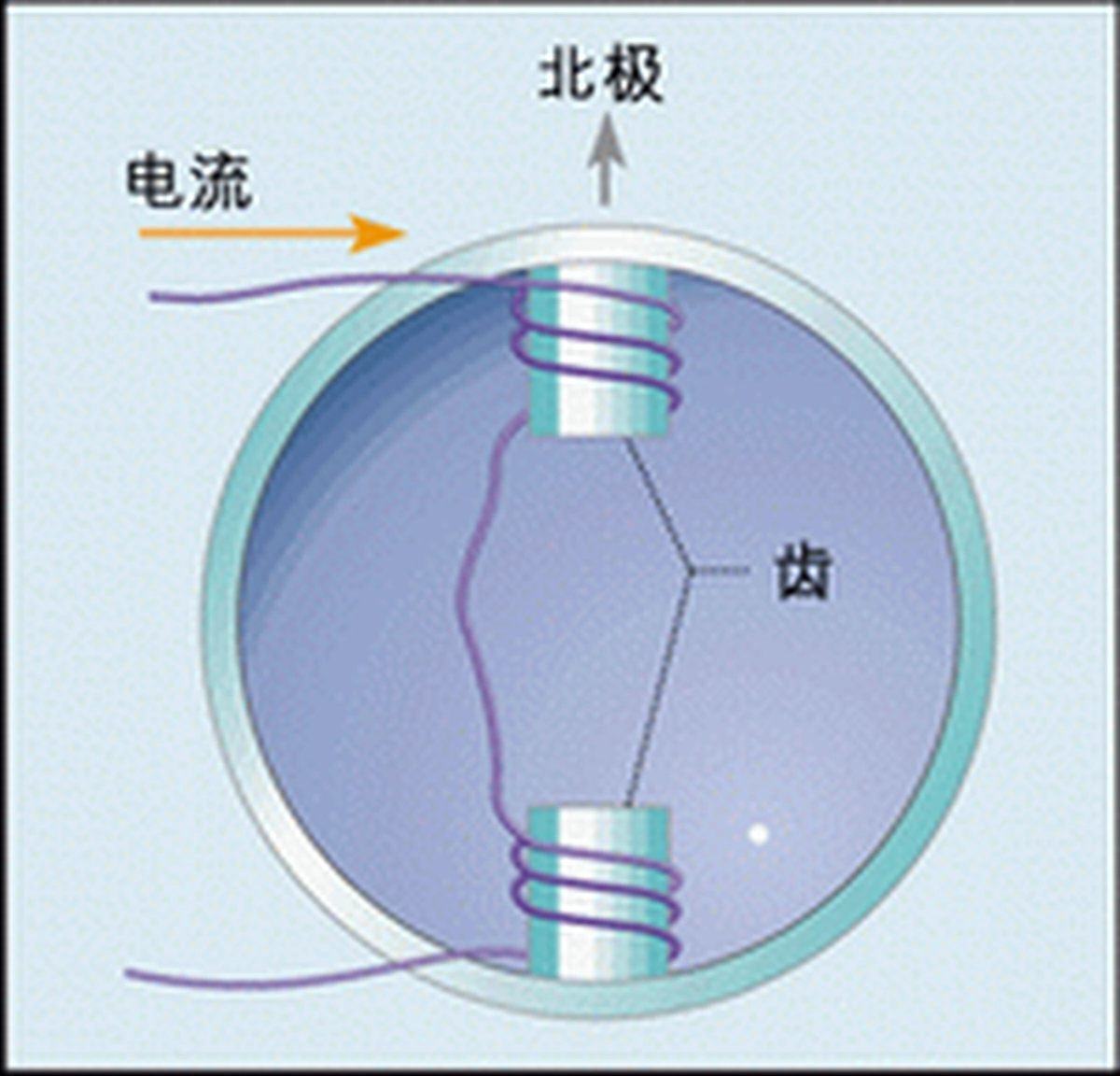
As shown in Figure 1, a stepper motor is driven by a set of coils wrapped around the teeth of the motor stator. This wire wound around the teeth is called a winding, coil, or phase. If the direction of current flow in the coils is as shown in Figure 1, and we are looking down from the top of the motor to the top of the teeth and slots, then the current is flowing in a counterclockwise direction around both teeth and slots. According to Ampere's law and the right-hand criterion, such a current produces a magnetic field with the north pole up.
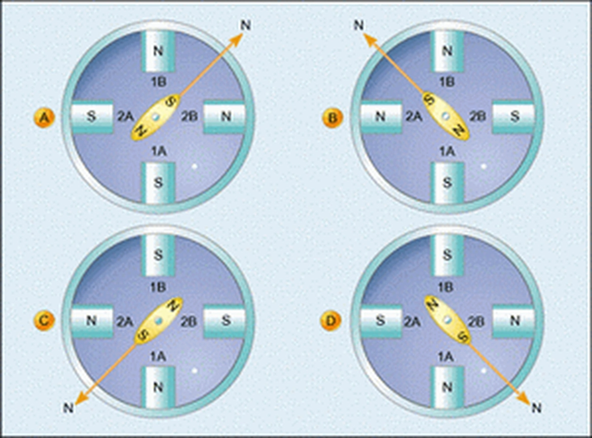
Now suppose we construct a motor with two windings wound on the stator and a built-in permanent magnet capable of rotating arbitrarily about the center, this rotatable part is called the rotor. Fig. 2 gives a simple motor called a two-phase bipolar motor because there are two windings on its stator and its rotor has two magnetic poles.

If we deliver current to winding 1 in the direction shown in Fig. 2a, and no current flows in winding 2, then the south pole of the motor rotor will naturally point towards the north pole of the stator magnetic field, as shown in the diagram.
Suppose again that we cut off the current in winding 1 and deliver current to winding 2 in the direction shown in Fig. 2b, then the magnetic field of the stator will point to the left, and the rotor will rotate with it, in line with the direction of the magnetic field of the stator.
Next, we cut off the current in winding 2 and deliver the current to winding 1 in the direction shown in Fig. 2c. Note: the current in winding 1 flows in the opposite direction to that shown in Fig. 2a. The north pole of the stator's magnetic field then points down, which causes the rotor to rotate and its south pole to point down.
Then we cut off the current in winding 1 again and feed the current to winding 2 in the direction shown in Fig. 2d, whereupon the magnetic field of the stator will again point to the right, causing the rotor to rotate, with its south pole also pointing to the right.
Finally, we again cut off the current in winding 2 and deliver the current to winding 1 as shown in Fig. 2a, whereupon the rotor will return to its original position.At this point, we have completed one cycle of electrical excitation of the motor windings and the motor rotor has rotated one full revolution. In other words, the electrical frequency of the motor is equal to the mechanical frequency of its rotation.
If we use 1 second to complete the sequence of the 4 steps shown in Figure 2, then the electrical frequency of the motor is 1Hz. Its rotor rotates for a week, and therefore its mechanical frequency is also 1Hz. In short, a two-phase stepper motor electrical frequency and mechanical frequency of the relationship between the following formula can be expressed:
fe=fm*P/2 (1)
where fe represents the electrical frequency of the motor, fm represents its mechanical frequency, and P represents the number of equidistant magnetic poles of the motor rotor.We can also see from Fig. 2 that each step of the operation rotates the rotor by 90°, i.e., the number of degrees of rotation caused by each step of the operation of a two-phase stepper motor can be expressed by the following equation:
1 step= 180°/P (2)
From equation (2), a bipolar motor can rotate 180°/2 = 90° for each action, which corresponds exactly to what we see in Figure 2. In addition, the equation shows that the higher the number of poles in the motor, the higher the stepping accuracy. It is common to find biphasic stepper motors with a number of poles between 12 and 200, and these motors have stepping accuracies between 15° and 0.9°.
The example given in Figure 3 is a biphase six-pole stepper motor containing three permanent magnets and thus six magnetic poles.
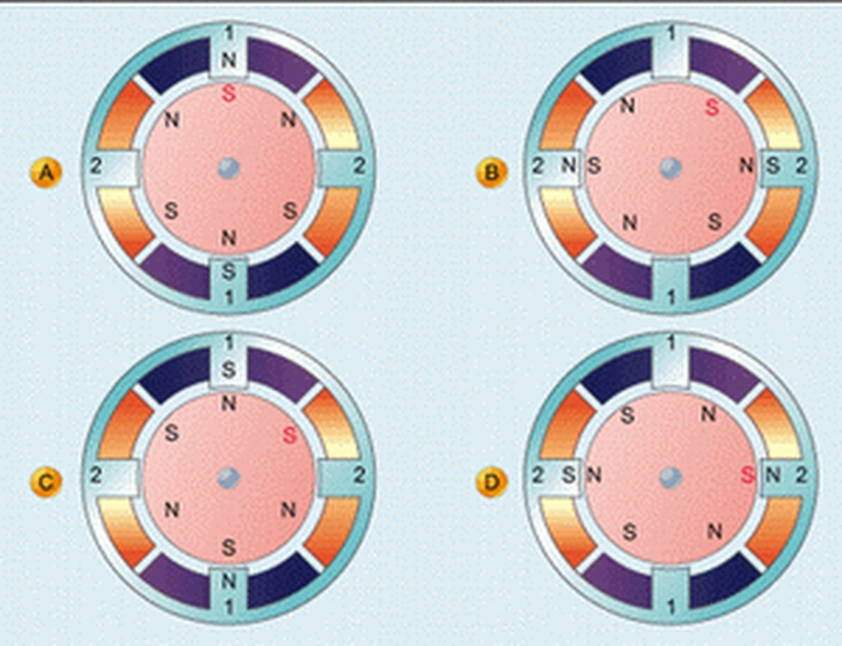
In the first step, as shown in Fig. 3a, we apply a voltage to winding 1, which produces a magnetic field in the stator with the north pole pointing towards its top, so that the south pole of the rotor (the red "S" end of Fig. 3a) is turned towards the top of the figure.
Next, in Fig. 3b, we apply a voltage to winding 2, and a magnetic field is generated in the stator with the north pole pointing to its left. As a result, one of the nearest south poles of the rotor turned to the left of the figure, i.e., the rotor turned clockwise by 30°.
In the third step, in Fig. 3c, we apply another voltage to winding 1, which produces a magnetic field in the stator with a north pole pointing to the lower part of the figure, thus rotating the rotor another 30° clockwise to the position shown in Fig. 3c.
In Fig. 3, we apply a voltage to winding 2 to produce a magnetic field in the stator with the north pole pointing to the right side of the stator, which again causes the rotor to rotate 30° clockwise to the position shown in Fig. 3d.
Finally, we apply another voltage to winding 1 to produce a magnetic field with the north pole pointing upwards of the stator as shown in Fig. 3a, causing the rotor to rotate clockwise by 30°, ending one electrical cycle. In this way, it can be seen that the 4 steps of electrical excitation caused a mechanical rotation of 120°. That is, the electrical frequency of this motor is three times the mechanical frequency, a result that is consistent with Equation (1). In addition, we can also see from Fig. 3 and Equation (2) that the rotor of this motor rotates 30° per step.
The torque of the motor can also be increased if the current is delivered to both windings at the same time, as shown in Fig. 4. At this point, the magnetic field at the motor stator is the vector sum of the fields generated by each of the two windings, and although this field still only rotates the motor by 90° with each action, as it does in Figs. 2 and 3, it is stronger at this point than it would have been if we had excited one winding alone because we have excited both motor windings at the same time. Since this magnetic field is the vector sum of the two perpendicular fields, it is equal to 2 x 1.414 times the field of each of the individual fields, and thus the torque applied by the motor to its load increases proportionally.
Sequence of excitation of a motor
Now that we know that a series of excitations will cause the stepper motor to rotate, the next step is to design the hardware to implement the desired stepping sequence. A piece of hardware (or a set of devices that combines hardware and software) that allows the motor to move is called a motor driver.How we excite the windings of a two-phase motor to rotate the motor rotor can be seen in Figure 4, where the winding taps within the motor are labeled 1A, 1B, 2A, and 2B., where 1A and 1B are the two taps of winding 1, and 2A and 2B, are the two taps of winding 2.
First, a positive voltage is applied to legs 1B and 2B, and 1A and 2A are grounded. Then, a positive voltage is applied to legs 1B and 2A while grounding 1A and 2B, a process that really depends on the direction in which the wires are wound around the notches, assuming that the wires are wound in the direction described in the previous section. Proceeding sequentially, we obtain the excitation sequence summarised in Table 1, where "1" denotes a positive voltage and "0" denotes ground.
There are two possible ways for current to flow in the motor windings, and such motors are called bipolar motors and bipolar drive sequences. Bipolar motors are usually driven by a circuit called an H-bridge, and a circuit connecting the H-bridge to the two taps of a stepper motor is given in Figure 5.
Figure 5 H-bridge circuit that can be used to drive each winding of a motor
The H-bridge is connected through a resistor to a DC supply with a fixed voltage (the amplitude of which can be selected according to the requirements of the motor), and the circuit is then connected to the two taps of the winding through four switches (labeled S1, S2, S3, and S4). The distribution of this circuit looks a bit like a capital H, hence the name H-bridge.
As can be seen from Table 1, to excite this motor, the first step should be to set tap 2A to logic 0 and 2B to logic 1, whereupon we can close the switches S1 and S4 and disconnect the switches S2 and S3. next, it is necessary to set tap 2A to logic 1 and 2B to logic 0, whereupon we can close S2 and S3 and disconnect S1 and S4. Similarly, in the third step, we can close S2, and S3 and disconnect S1 and S4, and in the fourth step, we can close S1, and S4 and disconnect S2, and S3.
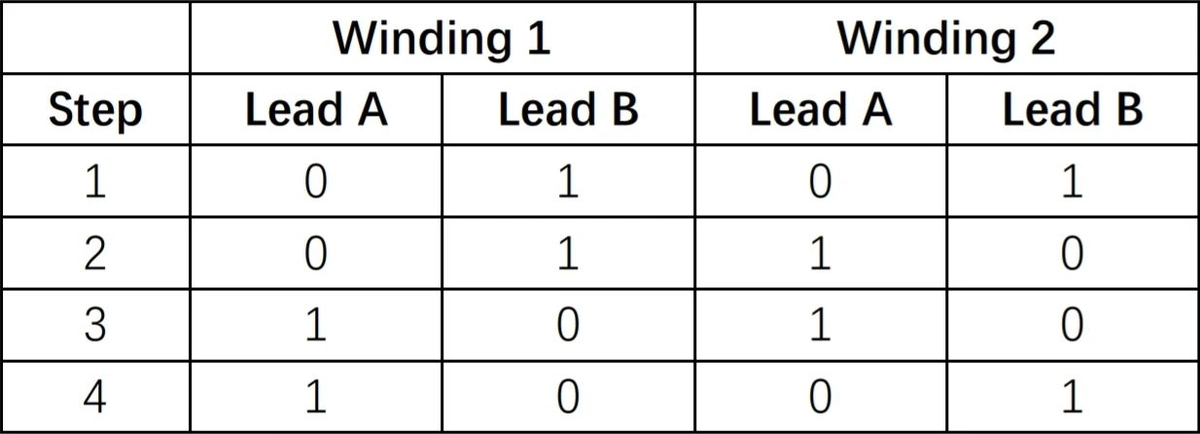
The method of excitation for winding 1 is no different, using a pair of H-bridges to produce the desired sequence of excitation signals. Table 2 shows where the switches are located at each step in the excitation process.
Note that if R=0 and switches S1 and S3 are accidentally closed at the same time, the current flowing through the switches will reach infinity. At this point, not only will the switches be burned out, but the power supply may be damaged as well, hence the use of a non-zero resistance resistor in the circuit. Although this resistor introduces a certain amount of power consumption and also reduces the efficiency of the motor driver, it provides short-circuit protection.
Unipolar motors and their drivers
We have already discussed bipolar stepper motors and drivers. Unipolar motors are similar to bipolar motors, except that in a unipolar motor, the only thing accessible externally is the center tap of each winding, as shown in Figure 6. We will label the tap from the top of the winding as Tap B, the bottom tap as Tap A, and the center tap as Tap C.
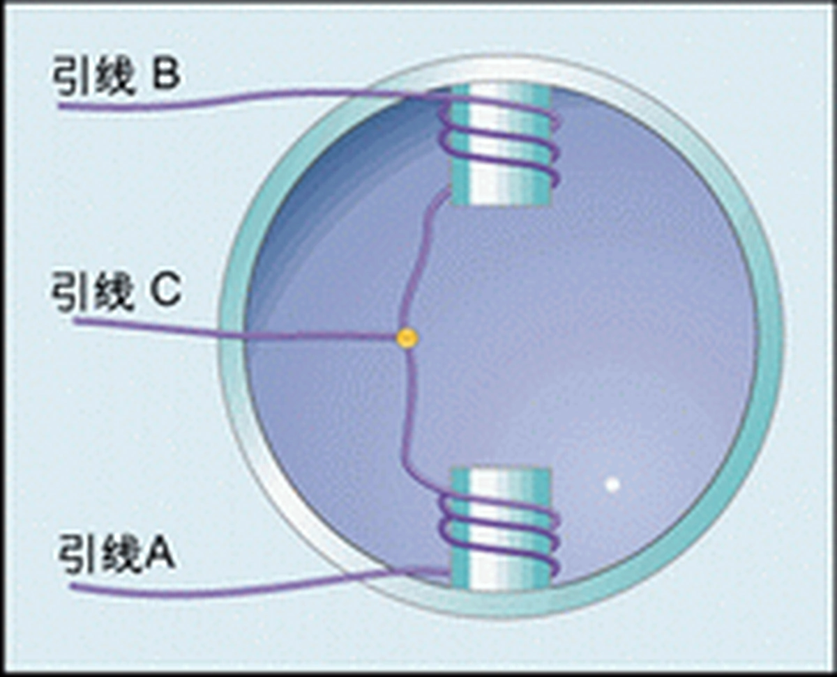
Sometimes we encounter motors with unlabelled taps. If we are clear about the construction of stepper motors, it is easy to identify which taps belong to which winding by measuring the resistance between the taps. The impedance between the taps of different windings is usually infinity. If the impedance between taps A and C is measured to be 100 ohms, then the impedance between taps B and C should also be 100 ohms, and the impedance between A and B should be 200 ohms. The impedance value of 200 ohms is called the winding impedance.
Figure 7 gives a single-phase drive circuit for a unipolar motor. It can be seen that when S1 is closed and S2 is open, the current will flow through the motor winding from right to left; while when S1 is open and S2 is closed, the current flow changes to left to right. Thus, we can change the direction of the current flow with only two switches (whereas in a bipolar motor, four switches are required to do so). Table 3 shows the position of the switches at each step of excitation in the unipolar motor drive circuit.
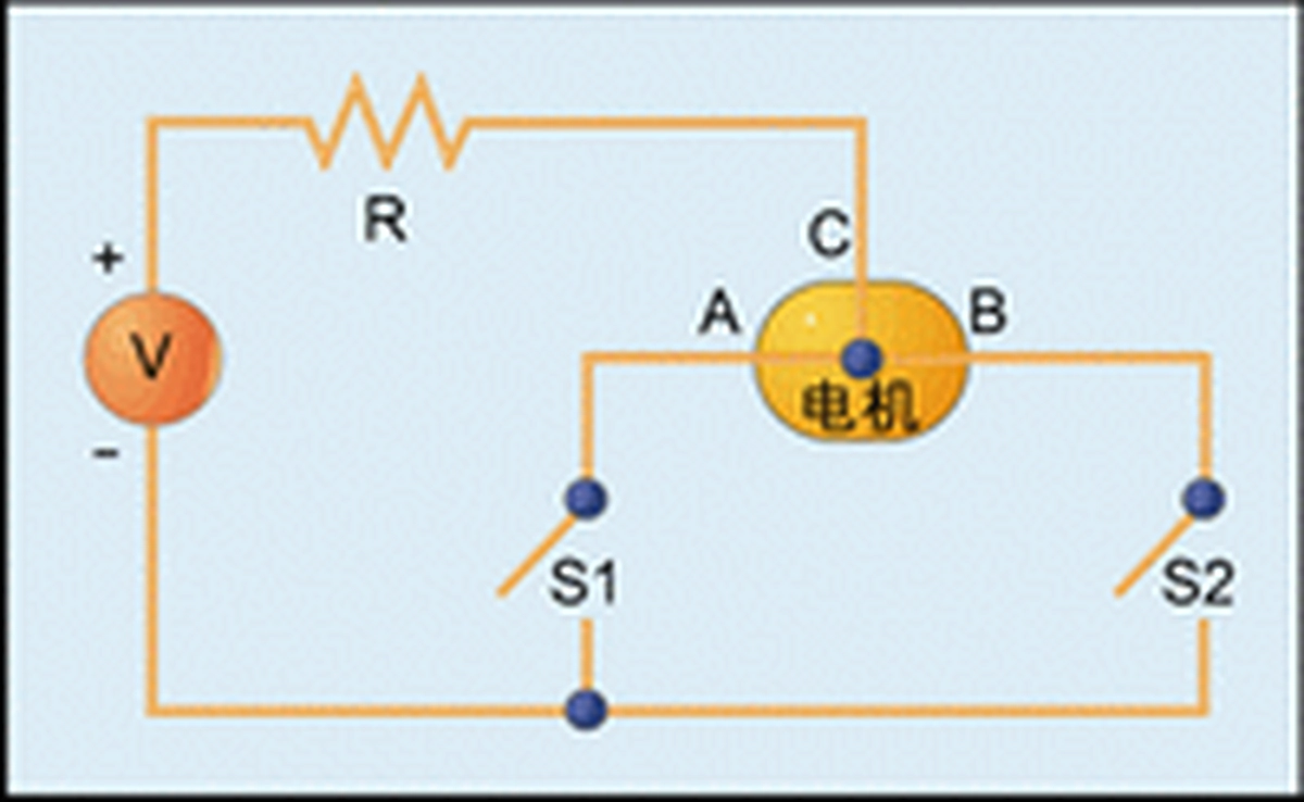
Although a unipolar motor driver is relatively simple to control, it is more complex than a bipolar motor because of the use of a center tap in the motor, and it is usually more expensive than a bipolar motor. In addition, because current flows through only half of the motor windings, a unipolar motor can produce only half of the magnetic field.
Knowing how unipolar and bipolar motors are constructed when we come across a motor with no labeled taps and no datasheet, we are able to deduce the relationship between the taps and the windings for ourselves. A motor with 4 taps is a two-phase bipolar motor, and we can tell which two taps belong to the same winding by measuring the impedance between the wires. A motor with 6 taps may be a two-phase unipolar motor or a three-phase bipolar motor, which can be determined by measuring the impedance between the wires.
Motor Control
The motor control theory discussed earlier in this paper can be implemented using a full hardware scheme, or it can be implemented using a microcontroller or DSP. Figure 8 illustrates how a biphase unipolar motor can be controlled using transistors as switches. The base of each transistor is connected to one of the digital outputs of the microcontroller through a resistor, which can be from 1 to 10M ohms, to limit the current flowing into the base of the transistor. The emitter of each transistor is grounded and the collector is connected to the 4 taps of the motor winding. The center taps of the motor are all connected to the positive side of the supply voltage.
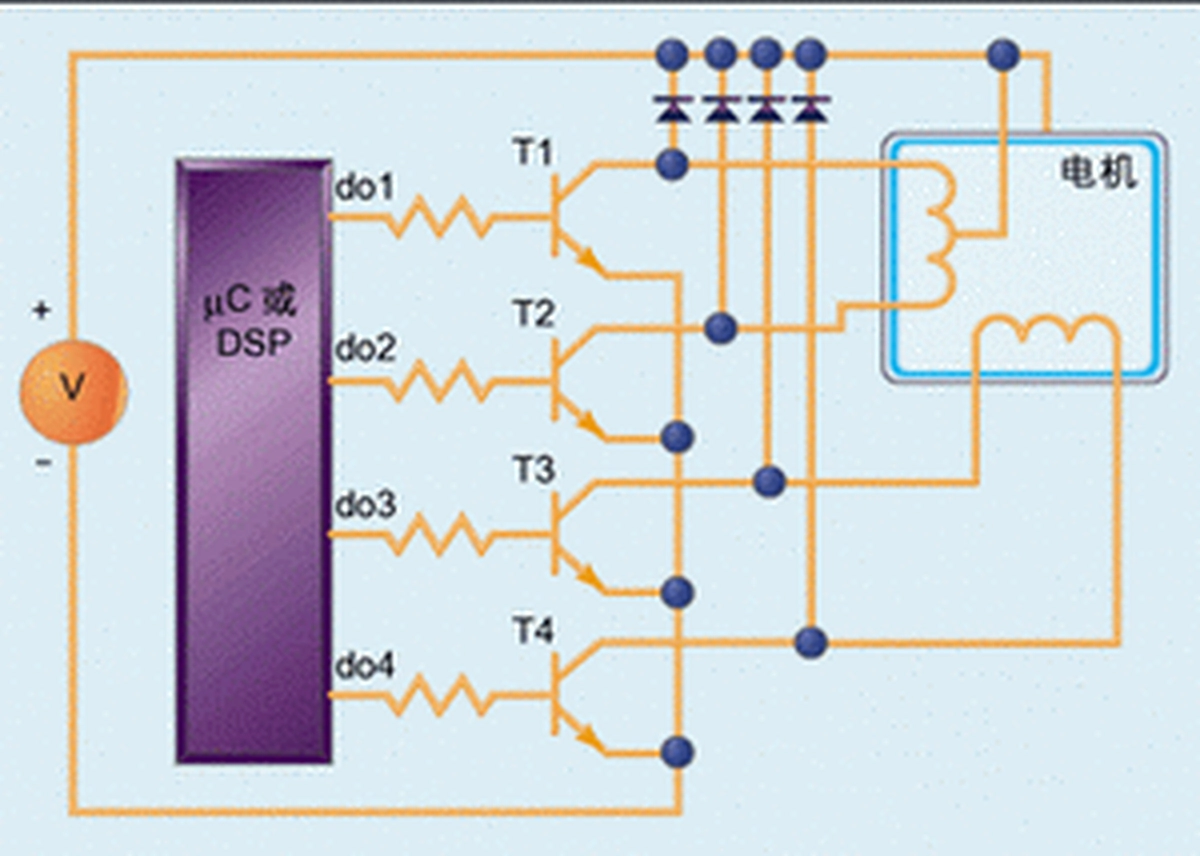
The collector of each transistor is connected to a voltage source through a diode to protect the transistor from being burned by the induced current on the motor winding as it rotates. As the rotor rotates, an induced voltage occurs on the motor windings, and if the transistor collector is not connected to the voltage source via a diode, the current caused by the induced voltage will surge into the collector of the transistor.
As an example, suppose the digital output do1 is high and do2 is low, whereupon do1 will cause transistor T1 to conduct, and current will flow from +V through the center tap and the base of T1, and then be output from the emitter of T1. However, at this point do2 is disconnected, so current can’t flow through T2. reasoning in this way gives us a clear idea of the sequence of hardware and digital outputs required to drive the motor. The software can then be written for the most compliant microcontroller or DSP to implement these sequences.
Firmware control
I implemented the motor controller talked about above on a MicrochipPIC16F877 using a 1N4003 diode and a 2SD1276A Darlington transistor. bits 0 to 3 of the PIC's PortA are used for digital outputs. The motor is a 5V biphase unipolar motor (made by Airpax [Thomson], model M82101-P1) and the same 5V supply is used to power both the PIC and the motor. However, in a real application, to avoid introducing noise to the power signals of the microcontroller, it is recommended that you still use separate power supplies for the motor and the microcontroller.
Picture 9 gives the assembly source code of the control programme which rotates the motor once every 50 ms. First, the program initialises the digital outputs of the microcontroller to the values in the first step of Table 4, and then cycles the digital signals every 50 milliseconds (this time constant is defined by the constant waitTime in the program) in the correct order.
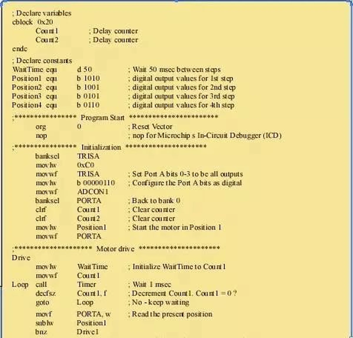
The motor used is a 24-pole motor, i.e., each step of the output can control the motor to rotate 180°/24 = 7.5°. The motor rotates 7.5° every 50 milliseconds, or one week every 2.4 seconds. If the constant waitTime is reduced by half, the motor will rotate twice as fast. However, because the rotor is limited by inertia, friction, and other mechanical constraints, there is an upper limit to the motor's speed, and when the stator's magnetic field rotates too fast, the rotor's speed can’t keep up, resulting in the motor's rotation not being able to keep up either, and it begins to skip (skipping). If the ohmic aitTime is lowered at this point, the motor is likely to simply stop rotating.
Conclusion
In addition to the two-phase motors that are the focus of this article, there are other types of stepper motors, such as three-phase stepper motors or four-phase stepper motors. There are also two-phase stepper motors that have only one centre tap that is connected to the centre of both windings, and these types of stepper motors have five taps leading out externally. Again, stepper motors are not the only members of the motor family, the oldest and simplest motors are direct current (DC) motors. Early DC motors used brushes, which are no longer popular. Today's common brushless DC motors are DC motors that use electronic circuits instead of brushes for commutation. There is no brush aging problem in these motors, so their life span is much longer than that of a brushed DC motor. There is also a kind of induction motor, its working principle is completely different from the stepping motor or DC motor. DC motors use a DC voltage source, while induction motors use an alternating current (AC) voltage source, and the rotation of the rotor and stator magnetic field is synchronised in stepper and DC motors, while the rotor speed in induction motors lags behind the stator magnetic field speed.

Leave a Reply